• API
  • 中文

40000

Quantity Price

1 10 100 1000 2500 Updated
* 0402YD104KAT2A 0 CNY 0.02731
* 0402YC223KAT2A 0 CNY
* 0402YD104KAT2A 0 CNY 0.118
* 0402YJ100GBSTR 0 CNY 7.403 7.085
* 0402YC102KAT2A 0 CNY
* 0402YC103KAT2A 0 CNY 0.079
* 0402YC103JAT2A 0 CNY
* 0402YG104ZAT2A 0 CNY 0.118
* 0402YC223JAT2A 0 CNY 1.045 1.022
* 0402YJ8R2BBSTR 0 CNY 16141.48
* 0402YD105KAT2A 0 CNY
* 0402YC153KAT2A 0 CNY 0.377
* 0402YC123KAT2A 0 CNY 0.184
* 0402YC102JAT2A 0 CNY
* 0402YJ100FBSTR 0 CNY 7.292
* 0402YC103KAT2A 0 USD
* 0402YC102KAT2A 0 USD
* 0402YC104KAT2A 0 USD
* 0402YD104KAT2A 0 USD
* 0402YC223KAT2A 0 USD
* 0402YC104KAT2A 0 USD
* 0402YC223KAT2A 0 USD
* 0402YC103KAT2A 0 USD
* 0402YC102KAT2A 0 USD
* 0402YC103JAT2A 0 USD
* 0402YC104KAT2A 0 USD
* 0402YD104KAT2A 0 USD
* 0402YC223KAT2A 0 USD
* 0402YC103JAT2A 0 USD
* 0402YC104MAT2A 0 USD
* 0402YC123KAT2A 0 USD
* 0402YD473KAT2A 0 USD
* 0402YC104KAT2A 0 USD
* 0402YC472KAT2A 0 USD
* 0402YC102KAT2A 0 USD
* 0402YD104MAT2A 0 USD
* 0402YD473KAT2A 0 USD
* 0402YA100DAT2A 0 USD
* 0402YC103KAT2A 0 USD
* 0402YA220JAT2A 0 USD
* 0402YC153KAT2A 0 USD
* 0402YC103JAT2A 0 USD
* 0402YC102JAT2A 0 USD
* 0402YC223JAT2A 0 USD

26
Y5V Dielectric
General Specifications
Y5V formulations are for general-purpose use in a limited
temperature range. They have a wide temperature
characteristic of +22% –82% capacitance change over the
operating temperature range of –30°C to +85°C.
These characteristics make Y5V ideal for decoupling
applications within limited temperature range.
0805
Size
(L" x W")
3
Voltage
6.3V = 6
10V = Z
16V = Y
25V = 3
50V = 5
G
Dielectric
Y5V = G
104
Capacitance
Code (In pF)
2 Sig. Digits +
Number of
Zeros
Z
Capacitance
Tolerance
Z = +80 –20%
A
Failure
Rate
A = Not
Applicable
T
Terminations
T = Plated Ni
and Sn
2
Packaging
2 = 7" Reel
4 = 13" Reel
A
Special
Code
A = Std.
Product
PART NUMBER (see page 2 for complete part number explanation)
% Capacitance
+20
+10
0
-55 -35
-15 +5 +25 +45 +65 +85 +105
+125
Temperature °C
Temperature Coefficient
-60
-50
-40
-30
-20
-10
-70
-80
c/c (%)
+20
+40
0
0
% DC Bias Voltage
Capacitance Change
vs. DC Bias Voltage
-60
-40
-20
-100
-80
20
40
60
80
100
Insulation Resistance (Ohm-Farads)
1,000
10,000
100
0
+20 +30 +40 +60+50 +70 +80 +90
Temperature °C
Insulation Resistance vs. Temperature
|Z| (Ohms)
10,000
1,000
10,000
Frequency (Hz)
0.1 F - 0603
Impedance vs. Frequency
1
10
100
0.01
0.1
100,000
1,000,000
10,000,000
|Z| (Ohms)
1,000
10,000
Frequency (Hz)
0.22 F - 0805
Impedance vs. Frequency
1
10
100
0.01
0.1
100,000
1,000,000
10,000,000
|Z| (Ohms)
1,000
10,000
Frequency (Hz)
1 F - 1206
Impedance vs. Frequency
1
10
100
0.01
0.1
100,000
1,000,000
10,000,000
27
Y5V Dielectric
Specifications and Test Methods
Parameter/Test Y5V Specification Limits Measuring Conditions
Operating Temperature Range -30ºC to +85ºC Temperature Cycle Chamber
Capacitance Within specified tolerance
≤ 5.0% for ≥ 50V DC rating Freq.: 1.0 kHz ± 10%
Dissipation Factor
≤ 7.0% for 25V DC rating Voltage: 1.0Vrms ± .2V
≤ 9.0% for 16V DC rating For Cap > 10 μF, 0.5Vrms @ 120Hz
≤ 12.5% for ≤ 10V DC rating
Insulation Resistance
10,000MΩ or 500MΩ - μF, Charge device with rated voltage for
whichever is less 120 ± 5 secs @ room temp/humidity
Charge device with 300% of rated voltage for
Dielectric Strength No breakdown or visual defects 1-5 seconds, w/charge and discharge current
limited to 50 mA (max)
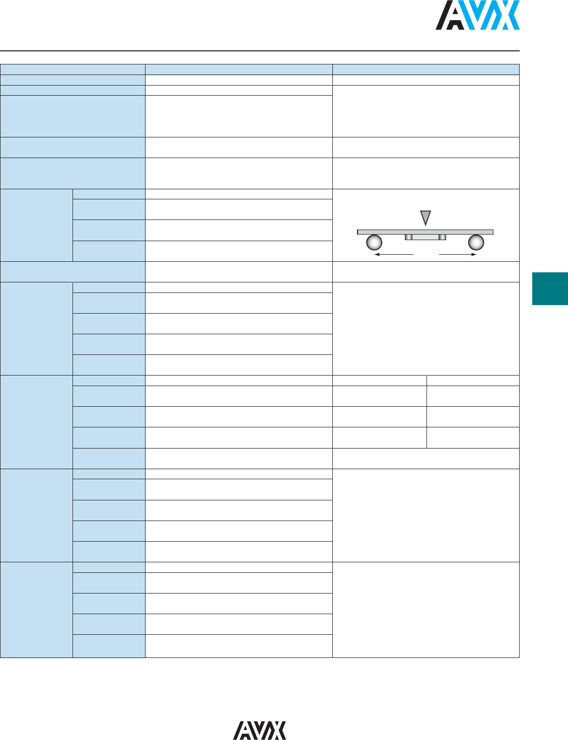
Appearance No defects Deflection: 2mm
Capacitance Test Time: 30 seconds
Resistance to Variation
≤ ±30%
Flexure Dissipation
Meets Initial Values (As Above)
Stresses Factor
Insulation
≥ Initial Value x 0.1
Resistance
Solderability
≥ 95% of each terminal should be covered Dip device in eutectic solder at 230 ± 5ºC
with fresh solder for 5.0 ± 0.5 seconds
Appearance No defects, <25% leaching of either end terminal
Capacitance
Variation
≤ ±20%
Dip device in eutectic solder at 260ºC for 60
Dissipation
Meets Initial Values (As Above)
seconds. Store at room temperature for 24 ± 2
Resistance to
Factor
hours before measuring electrical properties.
Solder Heat
Insulation
Meets Initial Values (As Above)
Resistance
Dielectric
Meets Initial Values (As Above)
Strength
Appearance No visual defects Step 1: -30ºC ± 2º 30 ± 3 minutes
Capacitance
Variation
≤ ±20% Step 2: Room Temp ≤ 3 minutes
Dissipation
Meets Initial Values (As Above) Step 3: +85ºC ± 2º 30 ± 3 minutes
Thermal
Factor
Shock
Insulation
Meets Initial Values (As Above) Step 4: Room Temp ≤ 3 minutes
Resistance
Dielectric
Meets Initial Values (As Above)
Repeat for 5 cycles and measure after
Strength 24 ±2 hours at room temperature
Appearance No visual defects
Capacitance
Variation
≤ ±30%
Dissipation
≤ Initial Value x 1.5 (See Above)
Load Life Factor
Insulation
≥ Initial Value x 0.1 (See Above)
Resistance
Dielectric
Meets Initial Values (As Above)
Strength
Appearance No visual defects
Capacitance
Variation
≤ ±30%
Load Dissipation
≤ Initial Value x 1.5 (See above)
Humidity Factor
Insulation
≥ Initial Value x 0.1 (See Above)
Resistance
Dielectric
Meets Initial Values (As Above)
Strength
Charge device with twice rated voltage in
test chamber set at 85ºC ± 2ºC
for 1000 hours (+48, -0)
Remove from test chamber and stabilize
at room temperature for 24 ± 2 hours
before measuring.
Store in a test chamber set at 85ºC ± 2ºC/
85% ± 5% relative humidity for 1000 hours
(+48, -0) with rated voltage applied.
Remove from chamber and stabilize at
room temperature and humidity for
24 ± 2 hours before measuring.
1mm/sec
90 mm
28
Y5V Dielectric
Capacitance Range
PREFERRED SIZES ARE SHADED
SIZE 0201 0402 0603 0805 1206 1210
Soldering
Reflow Only Reflow/Wave Reflow/Wave Reflow/Wave Reflow/Wave Reflow Only
Packaging
All Paper All Paper All Paper Paper/Embossed Paper/Embossed Paper/Embossed
(L) Length
mm 0.60 ± 0.03 1.00 ± 0.10 1.60 ± 0.15 2.01 ± 0.20 3.20 ± 0.20 3.20 ± 0.20
(in.) (0.024 ± 0.001) (0.040 ± 0.004) (0.063 ± 0.006) (0.079 ± 0.008) (0.126 ± 0.008) (0.126 ± 0.008)
(W) Width
mm 0.30 ± 0.03 0.50 ± 0.10 .81 ± 0.15 1.25 ± 0.20 1.60 ± 0.20 2.50 ± 0.20
(in.) (0.011 ± 0.001) (0.020 ± 0.004) (0.032 ± 0.006) (0.049 ± 0.008) (0.063 ± 0.008) (0.098 ± 0.008)
(t) Terminal
mm 0.15 ± 0.05 0.25 ± 0.15 0.35 ± 0.15 0.50 ± 0.25 0.50 ± 0.25 .50 ± 0.25
(in.) (0.006 ± 0.002) (0.010 ± 0.006) (0.014 ± 0.006) (0.020 ± 0.010) (0.020 ± 0.010) (0.020 ± 0.010)
WVDC 6.3 10 6 10 16 25 50 10 16 25 50 10 16 25 50 10 16 25 50 10 16 25 50
Cap 820
(pF) 1000 A
2200 A
4700 A
Cap 0.010 A A
(μF) 0.022 A
0.047 A C
0.10 C C G G K
0.22 G
0.33 G
0.47 C G G
1.0 C C G G N N N M M M N
2.2 C N
4.7 NPNN
10.0 NQQXQQ
22.0 QX
47.0
WVDC 6.3 10 6 10 16 25 50 10 16 25 50 10 16 25 50 10 16 25 50 10 16 25 50
SIZE 0201 0402 0603 0805 1206 1210
Letter ACEGJKMNPQXYZ
Max. 0.33 0.56 0.71 0.90 0.94 1.02 1.27 1.40 1.52 1.78 2.29 2.54 2.79
Thickness (0.013) (0.022) (0.028) (0.035) (0.037) (0.040) (0.050) (0.055) (0.060) (0.070) (0.090) (0.100) (0.110)
PAPER EMBOSSED
L
W
T
t

KYOCERA
CAP CER 0.047UF 16V Y5V 0402
DISCLAIMER: The information provided herein is solely for informational purposes. Customers must be aware of the suitability of this product for their application, and consider that variable factors such as Manufacturer, Product Category, Date Codes, Pictures and Descriptions may differ from available inventory.